中文
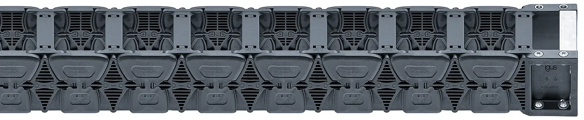

Series E61.80 | Openable along the inner and outer radius, from both sides | Inner height: 80mm
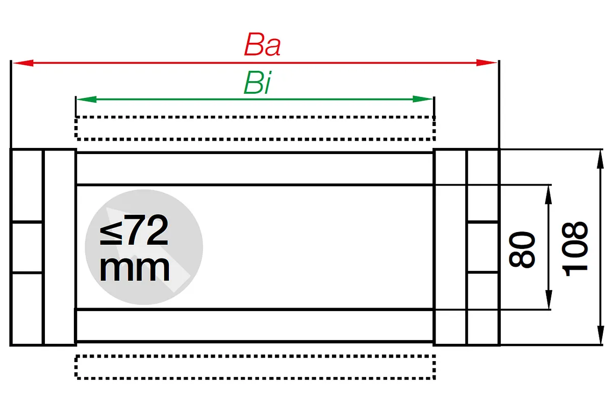
Inner height hi: 80mmInner width Bi: 50 - 600mmBend radii R: 150mmPitch: 65mmIPA cleanroom Class 1, cleanroom-compatible due to principle of low-abrasion for connectors, without pin and bore connectionHighly dynamicExtremely low vibration

Part No.

Inner width [Bi] [mm]

Bend radius [R] [mm]

Inner height [Hi]
80 mm

Max. cable diameter
36 mm

Opening principle
Can be opened along the inner and outer radius
Selection Info
Purchase method
Assembled PartsFully assembled chain (Including the separators)
Installation type
unsupported
Bracket
KMA, pivotingE61.800.05.12.A
Bracket Type
without C-profile
Mounting variant
A3
Dimensions
Fold
Inner height [Hi] [mm]
80 Fold
Inner width [Bi] [mm]
50 Fold
Outer height Ha [mm]
108 Fold
Outer width [Ba] [mm]
78 Fold
Bend radius [R] [mm]
150 Fold
Pitch [mm]
65 Fold
Chain links per metre
16 Fold
Max. cable diameter [mm]
36 Fold
H [mm]
508 Fold
D [mm]
301.5 Fold
K [mm]
605 Fold
DeltaHF [mm]
100 Fold
Velocity FLG unsupported max. [m/s]
20 Fold
Acceleration FLG max. [m/s²]
200 Fold
Maximum unsupported length [m]
5.25 Fold
Maximum long travel [m]
60 Fold
General properties
Fold
Opening principle
Can be opened along the inner and outer radius Fold
maximum fill weight [kg/m]
40 Fold
Colour
black Fold
Energy chain system
E6.1 Fold
Shipping weight (kg or kg/m)
3.15104 Fold
Temperature e-chain min. [°C]
-40 Fold
Temperature e-chain max. [°C]
120 Fold
Dynamic information
Fold
v max. unsupported (speed) [m/s]
20 Fold
Additional information and diagrams
Fold
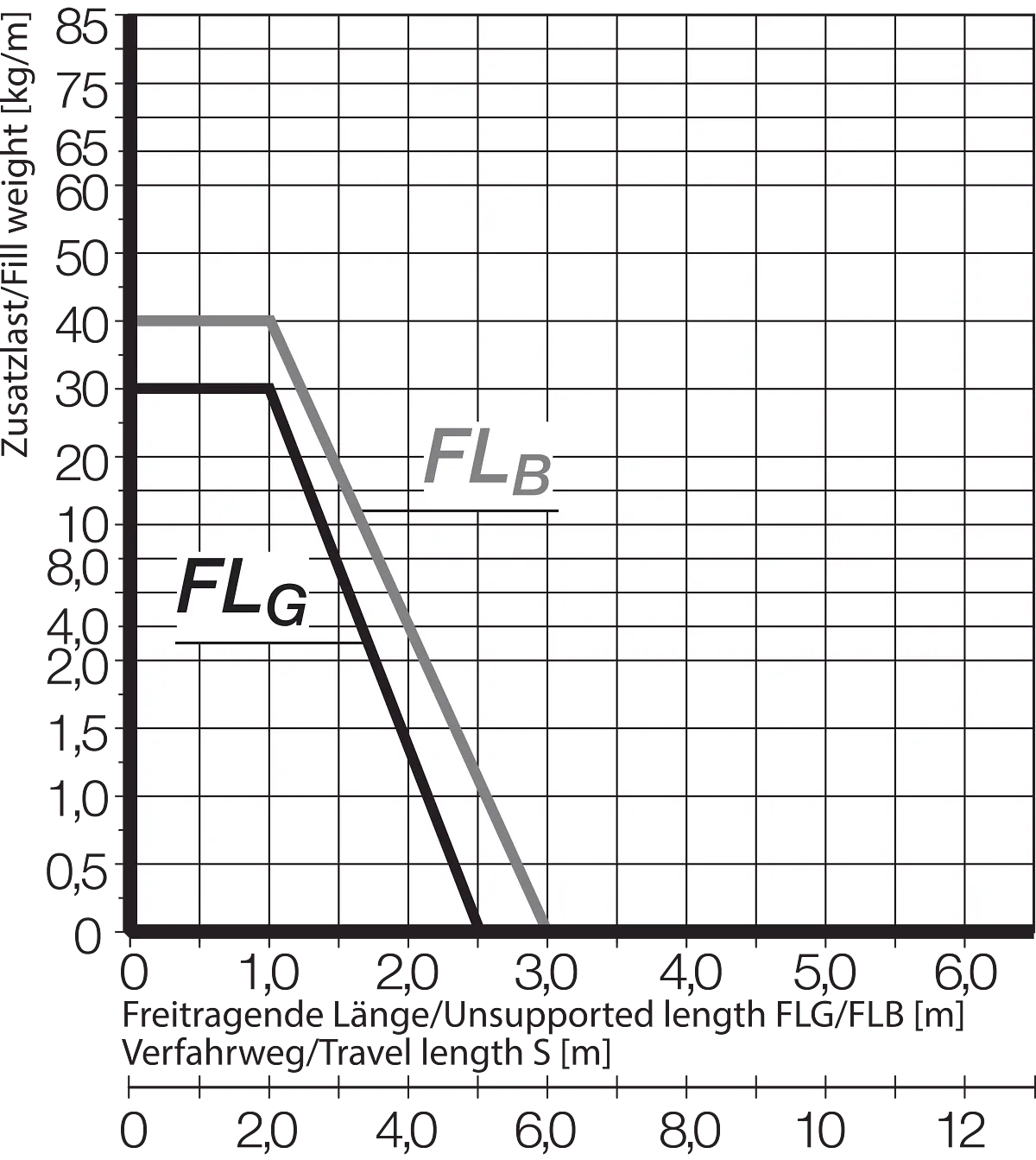
The unsupported length depends on fill weight
X axis: unsupported length in m FLB/FLG
Y axis: fill weight in kg/m
Lower scale: travel S in m
FLB = unsupported with permissible sag
FLG = unsupported with straight upper run
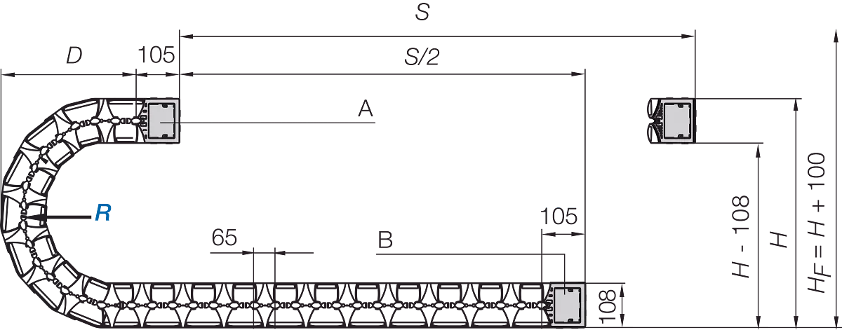
A = moving end, B = fixed end
Pitch: 65 mm
Chain links per m: 16 links/1000 mm
Travel: S
Chain length = S/2 + K
From 6 m to max. 60 m
Chain length = S/2+K2
Long travel - gliding (up to max. 60 m)
Here the e-chain® is used with the upper run gliding on the lower run. We recommend letting our engineers support you when planning this type of system. In case of travel lengths between 4.0m and 6m, we recommend a larger unsupported e-chain®.
A1 = moving end
A2 = fixed end
A3 = Guide trough with glide bar
A4 = Guide trough without glide bar
A5 = Total length of the guide trough



Sales Consulting


