中文
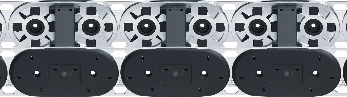


Hybrid energy chain YE.56 | Strong, vibration-proof and compact | Inner height: 56mm
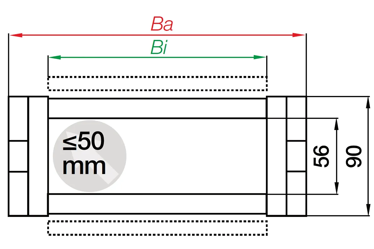
Inner height hi: 56mmInner width Bi: 100 - 600mmBend radius R: 100-500mmPitch: 91mmYE.56: 61% more unsupported length compared to the E4.56 seriesNo screws, rivets, or bolts which can become loose
under vibrationHigh tensile strengthEasy installation - plastic outer links with flange for easy e-chain link assembly

Part No.

Inner width [Bi] [mm]

Bend radius [R] [mm]

Inner height [Hi]
56 mm

Max. cable diameter
50 mm

Opening principle
Can be opened along the inner and outer radius
Selection Info
Purchase method
Assembled PartsFully assembled chain (Including the separators)
Installation type
unsupported
Bracket
Steel, pivotingYE.562.R100.1.12.A
Bracket Type
zinc-coated
Mounting variant
A3
Dimensions
Fold
Inner height [Hi] [mm]
56 Fold
Inner width [Bi] [mm]
100 Fold
Outer height Ha [mm]
90 Fold
Outer width [Ba] [mm]
124 Fold
Bend radius [R] [mm]
100 Fold
Pitch [mm]
91 Fold
Chain links per metre
11 Fold
Max. cable diameter [mm]
50 Fold
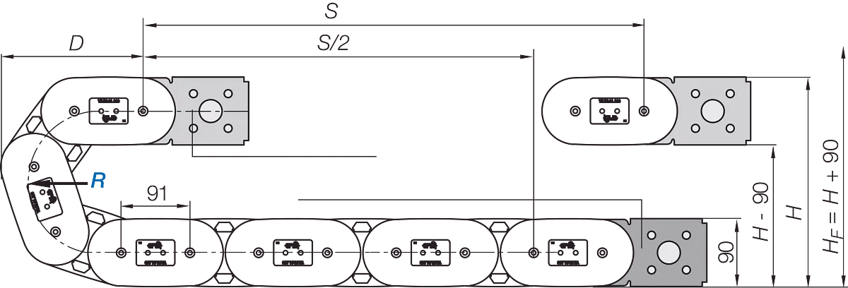
H [mm]
335 Fold
D [mm]
281.5 Fold
K [mm]
500 Fold
DeltaHF [mm]
90 Fold
Velocity FLG unsupported max. [m/s]
1 Fold
Acceleration FLG max. [m/s²]
1 Fold
Maximum unsupported length [m]
7.1 Fold
General properties
Fold
Opening principle
Can be opened along the inner and outer radius Fold
maximum fill weight [kg/m]
35 Fold
Energy chain system
YE Fold
Shipping weight (kg or kg/m)
6.46338 Fold
Temperature e-chain min. [°C]
-40 Fold
Temperature e-chain max. [°C]
120 Fold
Additional information and diagrams
Fold
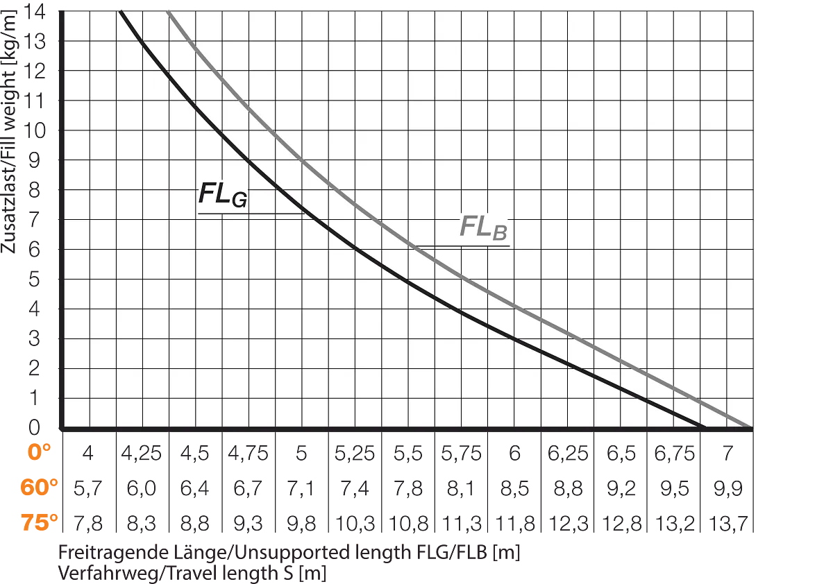
Unsupported length versus fill weight
X axis: unsupported length in m FLB/FLG
Y axis: fill weight in kg/m
Lower scale:
Unsupported lengths [m] at 0° / 60° / 75° inclination
FLG = unsupported with straight upper run
FLB = unsupported with permitted sag
Graph values provisional!
A=moving end, B=fixed end
Pitch: 91 mm per link
Chain links per m: 11
Travel: S
Chain length = LK = S/2 + K
Chain length = LK = S/2 + K
Long travels - gliding (up to max. 300 m)
Here, the e-chain® upper on lower run gliding in a guide trough is used. We recommend letting our engineers support you when planning this type of system. In case of travel lengths between 8.0m and 12m, we recommend a larger unsupported e-chain®.
A1 = moving end
A2 = fixed end
A3 = Guide trough with glide bar
A4 = Guide trough without glide bar
A5 = Total length of the guide trough

Sales Consulting

Scroll


